| General -> Accessories. | Handlebar risers for Storm ABS - Saddlemen bag quality? | | Previous page - [1],[2],[All] | | | Categories : |
|  | Topic : Turn signals become run/turn/stop plus brake light modulator |  |
| | | PapaSmurfMC | | Chaac |  |  | | Reg. Date | : | 03/10/2013 | | Posts | : | 871 | | Location | : | Philadelphia, Pennsylvania, United States |
|
| | Posted : 12 Apr 2014 - 17:40 Post title : Re: Turn signals become run/turn/stop plus brake light modulator (Re: PapaSmurfMC) | | | Posting this everywhere I mentioned the Signal Dynamics Dual Load Equalizer I used in my rear lighting mod. After finally getting the Bird out of the garage for the first time this season, I found I had the same issue reported by basaint2 of the rear LED signals working perfectly as long as the engine isn't running. I'm going to try so solve the problem with these equalizers but recommend to everyone to STAY AWAY FROM SIGNAL DYNAMICS DUAL LOAD EQUALIZER.
| 2013 Blue Marble Haze Thunderbird 1600 ABS
2009 Black Bonneville A1 ("Mag")
Buncha farkles
|
|
| | | bondage007 | | Set | |  | | Reg. Date | : | 18/07/2011 | | Posts | : | 263 | | Location | : | Glocester, Rhode Island, United States |
|
| | Posted : 17 May 2014 - 13:22 Post title : Re: Turn signals become run/turn/stop plus brake light modulator (Re: PapaSmurfMC) | | |
PapaSmurfMC wrote:
Part 1 (of 2) - Turn signals become run/turn/stop plus brake light modulator
As I've said in previous posts, I think one of the biggest shortcomings (in the TBird's very short list of shortcomings) is the less than ideal night time visibility. In the front, at least you can (and I have) add the Aux/Fog light bar. In the back, though, you've really only got the brake light and the license plate visible at night. If you live in a mixture of a rural and suburban area, like I do, all routes take you through hilly wooded areas with lots of blind curves as well as through mall and highway traffic.
So, high on my list of mods was converting my stock turn signals into run/turn/stop signals to increase my visibility profile. I also wanted to add a brake light modulator that would flash the brake light a few times and then stay on every time the brakes were applied to wake up the texters.
As always when you make a lighting change on your bike, first check state vehicle codes to make sure your changes are street-legal.
To make the changes I mentioned, there are a few considerations:
(1) As we all know, our turn signals are single-filament incandescent bulbs; this doesn't lend itself to easy functional upgrades. No matter what extra functions we put in there, we're going to have to run additional wires and we're going to need to find light sources of the right colors that fit in our signal housings or replace the signals completely. Don't know about you but I like the way the TBird's lights look and are built so I want to keep them.
(2) We'll need to somehow interrupt and tap into various parts of the stock wiring harness. I avoid cutting or piercing stock wiring at all costs. The goal here is to identify the stock connectors that carry the signals we want to reroute, find mating connectors and build our own intermediate wiring harness to do what we want without butchering the stock wires. This also lets us easily revert back to stock.
(3) We need to make sure we're not exceeding the power carrying capacity of the stock wires.
So, parts first. After lots of research and some previous experience, I chose Custom Dynamics Dynamic Cluster II LED clusters. These have very bright LEDs with a ring of amber LEDs surrounding a central core of red LEDs. This is what they actually look like, contrary to what my crappy camera will turn it into later.
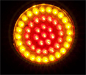
Separate wires control run (dim red), stop (bright red) and turn (amber); there's also a ground wire, of course. Because we're replacing the incandescent load with LEDs, we'll need a load equalizer for each side so our flash rate isn't affected; for that I went with a Signal Dynamics Dual Load Equalizer Module ($20). I normally prefer just replacing the turn signal relay with an LED-compatible relay but on my Bird (2013), the turn signal switching comes from the instrument panel circuitry; not accessible and not replaceable. Unlike just a power resistor, the Dual Load Equalizer is alarm system compatible, waterproof and handles 2 independent loads.
For the brake modulator, I chose the Signal Dynamics BackOff XP ($40). This modulator has multiple flashing modes, including hazard flashing. I'm keeping it simple and just using the simple flash-five-times-and-then-stay-on mode.
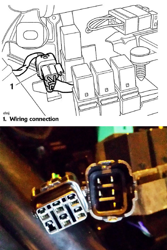
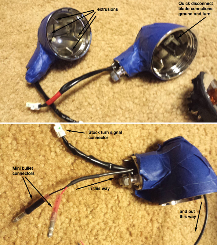
Finding the 6-pin weatherproof connectors that mate with the rear lighting harness was not easy but nothing's impossible. It's a Sumitomo HM 090 Series connector, found here, for $5.85: Link . The additional 2-pin weatherproof connector was easily found on eBay. If you don't want to change the internal turn signal connections (when replacing the stock bulb socket/reflector with the LED cluster), you'll need to acquire some crimp-type mini blade quick disconnects, another easy buy on eBay. You'll also need some small, narrow bullet connectors to terminate the run and stop wires coming from the LED clusters. They need to be narrow enough to fit through the turn signal mount in the fender along with the stock turn signal cable.
Another nit I have with my TBird is the lack of places to mount non-factory gizmos. We need a place to mount the BackOff XP and the Load Equalizer. Both devices are potted in a finned aluminum extrusion so they should be mounted in an area with some ventilation. They barely get warm in normal operation.
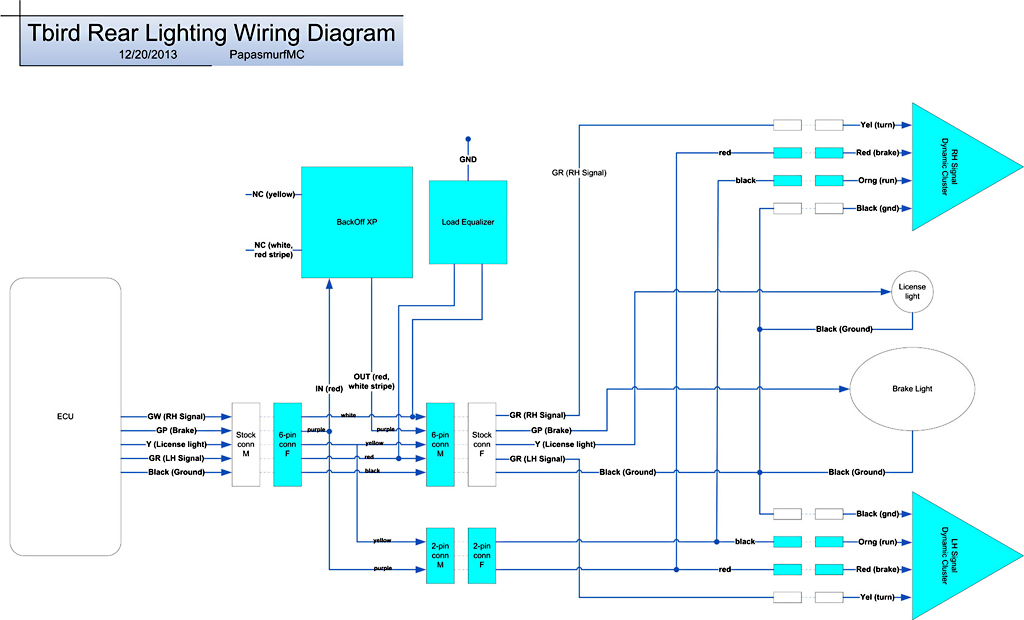
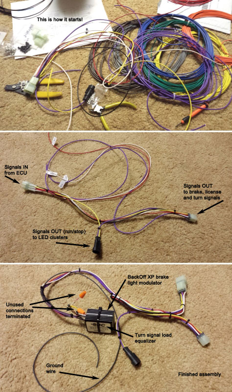
So first task was identifying stock connectors, tracing wires and drawing up a wiring diagram (and here it is). In the diagram, I've colored all newly added components blue (teal?); the uncolored components are stock. Adjacent rectangles with dashed connecting lines are connector male/female pairs. I color-coded my harness for easy identification and the colors I used are labeled in the diagram. There's nothing magic about the particular colors, they just need to be different.
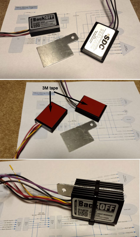
Next up is packaging the modulator and equalizer modules, finding a suitable mounting location and building the wiring harness. The modulator and equalizer are in identical packages and come with 3M double sided tape for mounting. Since they don't generate a lot of heat and what they do generate they don't dissipate through the taped bottom, it made sense to make a Signal Dynamics sandwich; an aluminum mounting plate sandwiched between the modulator and equalizer. The aluminum plate has a drilled tab extending beyond the extrusions to allow screw attachement to the frame. You want, of course, all the wires to exit on the same side of the extrusions. The sandwich fit nicely in a space on the right side between the relay group the battery box. There's an unused and unthreaded bolt hole on the battery box that worked out perfectly with a spacer to keep the sandwich from touching anything on any side.
Now the Signal Dynamics sandwich is ready to be attached to the cable harness, magically assembled by all the little gremlins you brought home on your ride bell. Skipping the details on this part because it's boring. Just use high quality connectors and wire and use the right crimping tool. Double and triple check your wiring against the diagram; check continuity with a meter. If you really want a connection by connection account of the cable assembly, let me know; the diagram says it all.
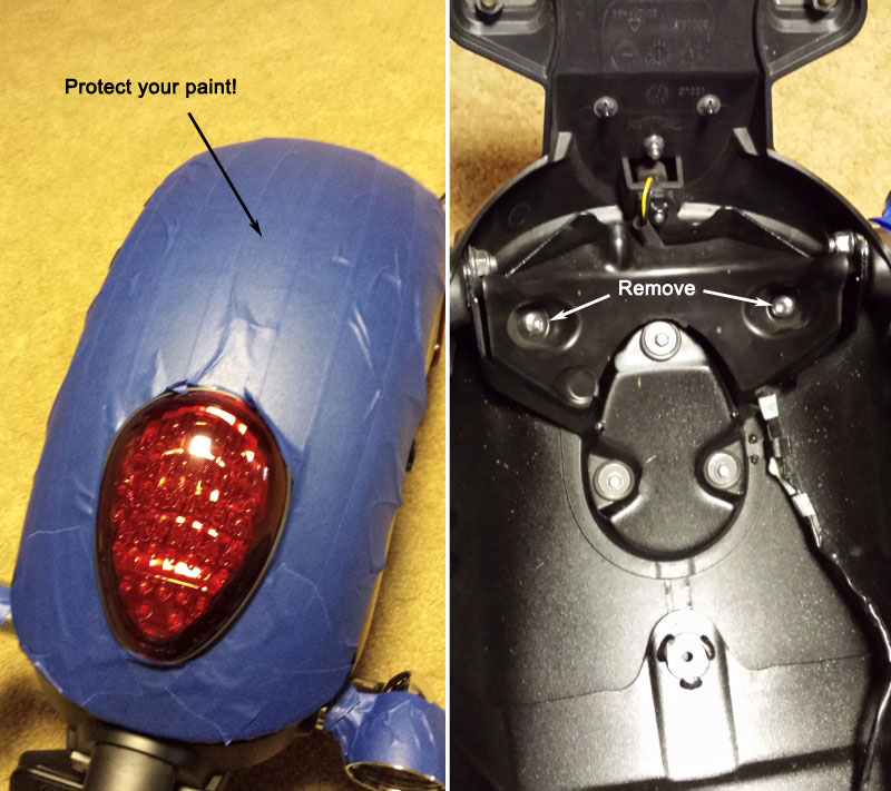
No way around it, you have to remove the rear mudguard (or "fender" as we say in the states). You'll need to disconnect the 6-pin connector positioned next to the bank of relays under the right side cover. This is also the connector our custom wiring harness will connect into. As rear fenders go, this one's a piece of cake to remove without trauma. The next very important thing to do is protect your paint. Use blue or green painters tape (not masking tape!) over the entire surface. You don't want to remount only to find swirlies and scratches. Tape the chrome areas of the turn signals, too.
Flip the protected fender on its back and remove the turn signals and the plastic guard covering the brake light. The brake light guard needs a spline tool to remove the bolts; I thought that was strange, considering hex is used everywhere else on the bike (that I've seen, at least).
Remove the clear lens covers of the signals and the bulbs then carefully pry the reflector from the turn signal housing. The plastic reflector is just press-fit into a rubber backing which itself is press-fit into the signal housing. The turn signal wires connect to the reflector/bulb socket with mini quick disconnect blades; they're easy to pop off. You'll need mating, insulated, crimp-type connections (both genders) to connect to these wires and the additional run and stop wires on the LED clusters inside the signal housing. You'll also need a small, narrow and preferably weather-proof single pin connector (like a small bullet connector) to terminate the additional wires coming from the LED cluster that must be snaked through the signal mount in the fender for connection under the brake light guard.
Continued, next post....
|
|
Hi Papa
Just finished my modified install of the dynamic cluster/knightriderz on saddlebags. Love them!! Will post with pics when able.
Now I'm thinking of adding the brake modulator (without load equalizer, still using stock signals).
What are the wires on the modulator "NC (yellow)" and "NC white" with red stripe connected to?
Thanks Again for all your help!!
Cheers
John
| 2010 Thunderbird Factory 1700, Uni Filter, Hogslayers, 7" Adjure Headlamp Lamp Upgrade
"When injustice becomes law rebellion becomes duty"
|
|
| | | PapaSmurfMC | | Chaac | | | | Reg. Date | : | 03/10/2013 | | Posts | : | 871 | | Location | : | Philadelphia, Pennsylvania, United States |
|
| | Posted : 17 May 2014 - 14:28 Post title : Re: Turn signals become run/turn/stop plus brake light modulator (Re: bondage007) | | | bondage007 wrote:
Just finished my modified install of the dynamic cluster/knightriderz on saddlebags. Love them!! Will post with pics when able.
Now I'm thinking of adding the brake modulator (without load equalizer, still using stock signals).
What are the wires on the modulator "NC (yellow)" and "NC white" with red stripe connected to?
|
|
Hi John. "NC" stands for "no connection"; they're unused unless you hook up the emergency flasher function with an external switch. Just clip the stripped wire tips off those leads and insulate so they don't short against anything (tape, wire nuts, whatever works).
Looking forward to your pics!
| 2013 Blue Marble Haze Thunderbird 1600 ABS
2009 Black Bonneville A1 ("Mag")
Buncha farkles
| | Post edited by PapaSmurfMC on 17 May 2014 - 16:08 |
|
| | | RallyFan43 | | Set | |  | | Reg. Date | : | 27/03/2015 | | Posts | : | 75 | | Location | : | Monroeville, PA, United States |
|
| | Posted : 01 Apr 2015 - 00:53 Post title : Re: Turn signals become run/turn/stop plus brake light modulator (Re: PapaSmurfMC) | | | Sorry to revive an older thread, but PapaSmurf do you have any idea what the connectors are called that are used to connect the stock turn signal wiring? Like what you have pictured here. I tried an eBay search, but came up empty thus far. I'm planning/thinking/pondering about installing the all red LED clusters in the rear signals, and if I can get those connectors that would make install fairly simple. Minus the load equalizer headache...

Also, as a head's up to any other Commander owners (and I'm assuming the LT is the same way) who have read over this thread, our install will not be quite this simple. As far as I can tell there is no connector for the rear wiring on the bike. It's all part of the main wiring harness. I was disappointed to discover this because I was hoping for a straight-forward connector install without the need to tap into any current wires.  
| JOSH
2014 Thunderbird Commander - Ravage 2.0
"Not all those who wander are lost"
|
|
| | | PapaSmurfMC | | Chaac | | | | Reg. Date | : | 03/10/2013 | | Posts | : | 871 | | Location | : | Philadelphia, Pennsylvania, United States |
|
| | Posted : 01 Apr 2015 - 04:01 Post title : Re: Turn signals become run/turn/stop plus brake light modulator (Re: RallyFan43) | | | RallyFan43 wrote: Sorry to revive an older thread, but PapaSmurf do you have any idea what the connectors are called that are used to connect the stock turn signal wiring? Like what you have pictured here. I tried an eBay search, but came up empty thus far. I'm planning/thinking/pondering about installing the all red LED clusters in the rear signals, and if I can get those connectors that would make install fairly simple. Minus the load equalizer headache...
.... |
|
Since I wasn't going to tap into those connectors, can't say I paid much attention to what they were, so I went back to my original photos to get a better look. Can't be absolutely certain but there's a reasonable chance they're 2-pin JWPF type connectors. You can get them here: Link
Won't cost you much to find out for sure, just $4.00 for a m/f pair plus shipping. If you get them, please let the rest of us know if they fit.
| 2013 Blue Marble Haze Thunderbird 1600 ABS
2009 Black Bonneville A1 ("Mag")
Buncha farkles
| | Post edited by PapaSmurfMC on 01 Apr 2015 - 04:01 |
|
| | | RallyFan43 | | Set | | | | Reg. Date | : | 27/03/2015 | | Posts | : | 75 | | Location | : | Monroeville, PA, United States |
|
| | Posted : 01 Apr 2015 - 10:50 Post title : Re: Turn signals become run/turn/stop plus brake light modulator (Re: PapaSmurfMC) | | |
PapaSmurfMC wrote:
RallyFan43 wrote: Sorry to revive an older thread, but PapaSmurf do you have any idea what the connectors are called that are used to connect the stock turn signal wiring? Like what you have pictured here. I tried an eBay search, but came up empty thus far. I'm planning/thinking/pondering about installing the all red LED clusters in the rear signals, and if I can get those connectors that would make install fairly simple. Minus the load equalizer headache...
.... |
|
Since I wasn't going to tap into those connectors, can't say I paid much attention to what they were, so I went back to my original photos to get a better look. Can't be absolutely certain but there's a reasonable chance they're 2-pin JWPF type connectors. You can get them here: Link
Won't cost you much to find out for sure, just $4.00 for a m/f pair plus shipping. If you get them, please let the rest of us know if they fit.
|
|
Sweet, thanks. You rock PapaSmurf! I will certainly post my findings when I get some in.
Also, regarding my other post, I took another look at my bike last night when I got home from work. There is in fact a connector for the rear lighting on the Commander, it's just in a different spot. I had incorrectly followed the wires before.
Here you can see that connector, it's located below the relays. Just have to move them out of the way a bit.

| JOSH
2014 Thunderbird Commander - Ravage 2.0
"Not all those who wander are lost"
|
|
| | | madi05 | | Set | | | Reg. Date | : | 10/08/2015 | | Posts | : | 75 | | Location | : | United States |
|
| | Posted : 13 Aug 2015 - 00:28 Post title : Re: Turn signals become run/turn/stop plus brake light modulator (Re: PapaSmurfMC) | | |
PapaSmurfMC wrote:
Posting this everywhere I mentioned the Signal Dynamics Dual Load Equalizer I used in my rear lighting mod. After finally getting the Bird out of the garage for the first time this season, I found I had the same issue reported by basaint2 of the rear LED signals working perfectly as long as the engine isn't running. I'm going to try so solve the problem with these equalizers but recommend to everyone to STAY AWAY FROM SIGNAL DYNAMICS DUAL LOAD EQUALIZER.
|
|
did u find a solution? im about to do this mod thanks for the share
|
|
| | | madi05 | | Set | | | Reg. Date | : | 10/08/2015 | | Posts | : | 75 | | Location | : | United States |
|
| | Posted : 13 Aug 2015 - 00:59 Post title : Re: Turn signals become run/turn/stop plus brake light modulator (Re: PapaSmurfMC) | | | i copied and pasted , can u send links to exact ones u used of all these little connectors etc. and size and how many i need to do the job , i really appreciate it
" The additional 2-pin weatherproof connector was easily found on eBay. If you don't want to change the internal turn signal connections (when replacing the stock bulb socket/reflector with the LED cluster), you'll need to acquire some crimp-type mini blade quick disconnects, another easy buy on eBay. You'll also need some small, narrow bullet connectors to terminate the run and stop wires coming from the LED clusters. They need to be narrow enough to fit through the turn signal mount in the fender along with the stock turn signal cable"
|
|
| | | PapaSmurfMC | | Chaac | | | | Reg. Date | : | 03/10/2013 | | Posts | : | 871 | | Location | : | Philadelphia, Pennsylvania, United States |
|
| | Posted : 13 Aug 2015 - 02:06 Post title : Re: Turn signals become run/turn/stop plus brake light modulator (Re: madi05) | | |
| madi05 wrote: did u find a solution? im about to do this mod thanks for the share |
|
The solution is to not bother with equalizers. The flash rate only increases 1Hz and equalizers just throw away the energy saved by the LEDs as heat.
| 2013 Blue Marble Haze Thunderbird 1600 ABS
2009 Black Bonneville A1 ("Mag")
Buncha farkles
|
|
| | | madi05 | | Set | | | Reg. Date | : | 10/08/2015 | | Posts | : | 75 | | Location | : | United States |
|
| | Posted : 13 Aug 2015 - 02:13 Post title : Re: Turn signals become run/turn/stop plus brake light modulator (Re: PapaSmurfMC) | | |
PapaSmurfMC wrote:
| madi05 wrote: did u find a solution? im about to do this mod thanks for the share |
|
The solution is to not bother with equalizers. The flash rate only increases 1Hz and equalizers just throw away the energy saved by the LEDs as heat. |
|
so that means no sdc load equalizer at all right? is the wiring going to be different if so which wires will be left out for the equalizer ,i see u said equalizers but i only read one being used along with the brake modulator which im planning on mimmicing , please lmk anything or other problems that arised i want to do this right the first time , lol
|
|
| | | PapaSmurfMC | | Chaac | | | | Reg. Date | : | 03/10/2013 | | Posts | : | 871 | | Location | : | Philadelphia, Pennsylvania, United States |
|
| | Posted : 13 Aug 2015 - 02:38 Post title : Re: Turn signals become run/turn/stop plus brake light modulator (Re: madi05) | | |
madi05 wrote:
i copied and pasted , can u send links to exact ones u used of all these little connectors etc. and size and how many i need to do the job , i really appreciate it
" The additional 2-pin weatherproof connector was easily found on eBay. If you don't want to change the internal turn signal connections (when replacing the stock bulb socket/reflector with the LED cluster), you'll need to acquire some crimp-type mini blade quick disconnects, another easy buy on eBay. You'll also need some small, narrow bullet connectors to terminate the run and stop wires coming from the LED clusters. They need to be narrow enough to fit through the turn signal mount in the fender along with the stock turn signal cable" |
|
The original post was more than a year and a half ago; those eBay links are long gone. The internal turn signal mini blade connectors are easily found; once you pull out the reflector on one of the signals and you'll see (and can measure, if necessary) them. Try 2.8mm spade terminals.
The mini bullet connectors are shown in the post photos; just shop for the smallest 22-18 AWG insulated bullets you can find; the more under 4mm diameter, the better.
Count on your bike being out of action for a few weeks. Unless you have another bike to ride, best to do a project like this over the winter.
| 2013 Blue Marble Haze Thunderbird 1600 ABS
2009 Black Bonneville A1 ("Mag")
Buncha farkles
|
|
| | | PapaSmurfMC | | Chaac | | | | Reg. Date | : | 03/10/2013 | | Posts | : | 871 | | Location | : | Philadelphia, Pennsylvania, United States |
|
| | Posted : 13 Aug 2015 - 02:44 Post title : Re: Turn signals become run/turn/stop plus brake light modulator (Re: madi05) | | | madi05 wrote:
so that means no sdc load equalizer at all right? is the wiring going to be different if so which wires will be left out for the equalizer ,i see u said equalizers but i only read one being used along with the brake modulator which im planning on mimmicing , please lmk anything or other problems that arised i want to do this right the first time , lol |
|
Not intending to sound critical but if you can't tell from looking at the schematic, you should rethink taking this on. I'm confident in the schematic but this isn't a kit and you're completely on your own. You don't have to be an engineer to do this mod but the equalizer is the easiest thing to leave out and the impact on wiring should be obvious.
| 2013 Blue Marble Haze Thunderbird 1600 ABS
2009 Black Bonneville A1 ("Mag")
Buncha farkles
| | Post edited by PapaSmurfMC on 13 Aug 2015 - 02:47 |
|
| | | madi05 | | Set | | | Reg. Date | : | 10/08/2015 | | Posts | : | 75 | | Location | : | United States |
|
| | Posted : 13 Aug 2015 - 02:49 Post title : Re: Turn signals become run/turn/stop plus brake light modulator (Re: PapaSmurfMC) | | |
PapaSmurfMC wrote:
madi05 wrote:
so that means no sdc load equalizer at all right? is the wiring going to be different if so which wires will be left out for the equalizer ,i see u said equalizers but i only read one being used along with the brake modulator which im planning on mimmicing , please lmk anything or other problems that arised i want to do this right the first time , lol |
|
Not intending to sound critical but if you can't tell from looking at the schematic, you should rethink taking this on. I'm confident in the schematic but this isn't a kit and you're completely on your own. |
|
i know i sound like noob , i have in fact a couple years ago changed my leds similar like this on my america i still have , but we spliced wires and used relay for the signal and no brake xp was used , and we used those small resistors at radio shack for the instrument panel lights blinkers , this is way more clean using connectors , im just wanting to when i get on it i have all the parts handy and dont want to get it wrong and have to wait for something to get here , btw i did the america in 4 hours front and back , i hope i wasnt making u feel uncomfortable
thanks for the help u already given
|
|
| | | PapaSmurfMC | | Chaac | | | | Reg. Date | : | 03/10/2013 | | Posts | : | 871 | | Location | : | Philadelphia, Pennsylvania, United States |
|
| | Posted : 13 Aug 2015 - 03:03 Post title : Re: Turn signals become run/turn/stop plus brake light modulator (Re: madi05) | | |
madi05 wrote:
i know i sound like noob , i have in fact a couple years ago changed my leds similar like this on my america i still have , but we spliced wires and used relay for the signal and no brake xp was used , and we used those small resistors at radio shack for the instrument panel lights blinkers , this is way more clean using connectors , im just wanting to when i get on it i have all the parts handy and dont want to get it wrong and have to wait for something to get here , btw i did the america in 4 hours front and back , i hope i wasnt making u feel uncomfortable
thanks for the help u already given |
|
That's why I say to do this over the winter. It's not going to keep you off the road if you have to order a part after disassembly so there's no rush. And speaking of relays, there's a follow-up thread, "Relay power for run/turn/stop signals" Link That's the schematic you want to use.
| 2013 Blue Marble Haze Thunderbird 1600 ABS
2009 Black Bonneville A1 ("Mag")
Buncha farkles
|
|
| | | RallyFan43 | | Set | | | | Reg. Date | : | 27/03/2015 | | Posts | : | 75 | | Location | : | Monroeville, PA, United States |
|
| | Posted : 28 Feb 2016 - 15:03 Post title : Re: Turn signals become run/turn/stop plus brake light modulator (Re: PapaSmurfMC) | | | PapaSmurfMC, sorry to revive an old thread (again), but after your install did you notice your turn signal running lights flickering at all? I previously installed the Custom Dynamics all-red rear signals made running lights with their SMART Triple Play, and just last night I finished installing their Dynamics Ringz in the front signals. Both are working well (aside from the expected fast flash) and are lit solid while the ignition is on but the bike is not running. However, when the bike is idling both the front rings and rear signals flicker just slightly. It's not bad just somewhat annoying and is setting off my OCD haha. Just wondering if you had any theories.
| JOSH
2014 Thunderbird Commander - Ravage 2.0
"Not all those who wander are lost"
|
|
| | | PapaSmurfMC | | Chaac | | | | Reg. Date | : | 03/10/2013 | | Posts | : | 871 | | Location | : | Philadelphia, Pennsylvania, United States |
|
| | Posted : 28 Feb 2016 - 22:01 Post title : Re: Turn signals become run/turn/stop plus brake light modulator (Re: RallyFan43) | | |
RallyFan43 wrote:
PapaSmurfMC, sorry to revive an old thread (again), but after your install did you notice your turn signal running lights flickering at all? I previously installed the Custom Dynamics all-red rear signals made running lights with their SMART Triple Play, and just last night I finished installing their Dynamics Ringz in the front signals. Both are working well (aside from the expected fast flash) and are lit solid while the ignition is on but the bike is not running. However, when the bike is idling both the front rings and rear signals flicker just slightly. It's not bad just somewhat annoying and is setting off my OCD haha. Just wondering if you had any theories. |
|
I have no flickering at all with engine running.
If the front and rear are flickering in sync with eachother and assuming you're not also driving the front turn signals off of the Triple Play, I'd drop a voltmeter across the battery (charging pigtail, if you've got one) and check that you've got 13.8 - 14.5 volts. Sounds like either your charging system isn't where it should be or you've got something loading (drawing too much current) the front and rear signals, also assuming you haven't installed load equalizers.
| 2013 Blue Marble Haze Thunderbird 1600 ABS
2009 Black Bonneville A1 ("Mag")
Buncha farkles
|
|
|
| |
| |
|